HYDROPNEUMATIC PRESSES

Speed, power and low environmental impact thanks to the synergy of two natural forces:
pneumatic and hydraulic
Speed, power and low environmental impact thanks to the synergy of two natural forces:
pneumatic and hydraulic
With compressed air only, they are capable of developing great force.
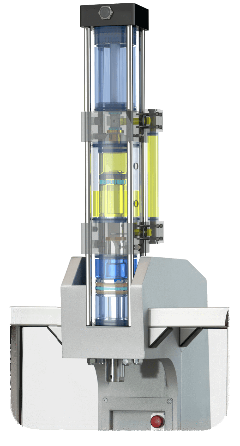
Thanks to the built-in hydropneumatic intensifier, they combine the approach and return speed of an air cylinder with the thrust force of a hydraulic cylinder.
 Bending
 Drawing
 Keying
 Assembly
 Clinching
 Trimming
 Chamfering
 Marking
 Straightening
 Riveting
 Pressing
 Cutting
 Compressing
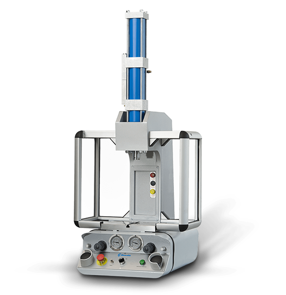
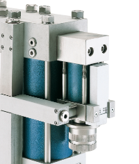
The Alfamatic power units AP and AX are the engine of the OP presses.
They consist of an air cylinder and a built-in hydraulic intensifier. As a result, the full stroke can be subdivided into two separate phases:
With 7 sizes and 6 configurations, thrust force from 14 kN to 420 kN, the OP series press line offers high productivity at low costs.
PRODUCTIVITY
With pneumatic approach and return and hydraulic pressing stroke, they guarantee reduced cycle times for unparalleled productivity.
ENERGY SAVING
The pneumatic / hydraulic separation allows to consume energy only when needed.
SILENCE
There are no hydraulic power units always in operation, for maximum comfort of use for the operator.
VERSATILITY OF USE
Many sizes and versions for a press cut to size of application.
MAXIMUM SECURITY
All the presses comply with the current strict accident prevention regulations.
They are safe and ready to use.
The presses are available in 6 configurations:
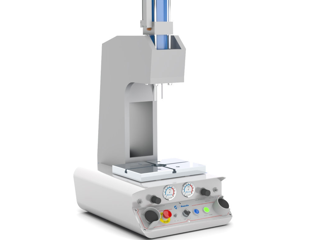
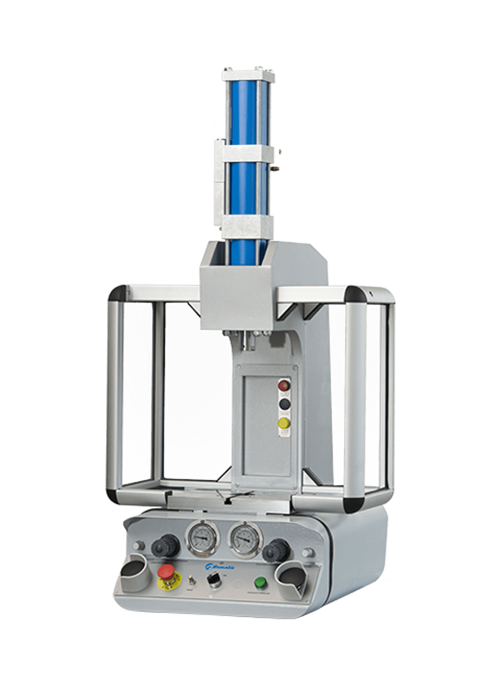
Monolithic C-shaped structure with low bending.
It is the most suitable structure when space is needed in a transversal sense.
In steel Fe 430 B UNI 7070, with surfaces protected by high resistance multilayer painting.

Low flex 2 column structure.
Structure in steel Fe 430 B UNI 7070.
Upper and lower plates protected by burnishing treatment.
Thick chromed columns.
Low flex 2-column structure and guided movable intermediate plate.
Structure in steel Fe 430 B UNI 7070.
Upper, lower and intermediate plates protected by burnishing treatment.
Thick chromed pillars.
Intermediate plate equipped with pneumatically operated fall arrest device.
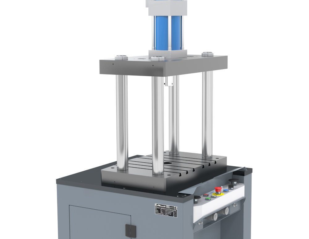
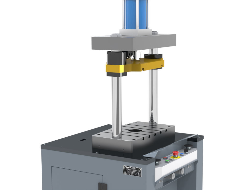
Low flex 4 column structure.
Structure in steel Fe 430 B UNI 7070.
Upper and lower plates protected by burnishing treatment.
Thick chromed columns.
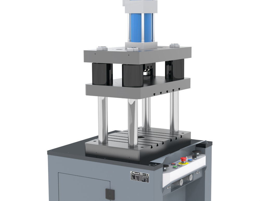
Low-flex 4-post structure and guided movable intermediate plate.
Structure in steel Fe 430 B UNI 7070.
Upper, lower and intermediate plates protected by burnishing treatment.
Thick chromed columns.
Intermediate plate equipped with pneumatically operated fall arrest device.
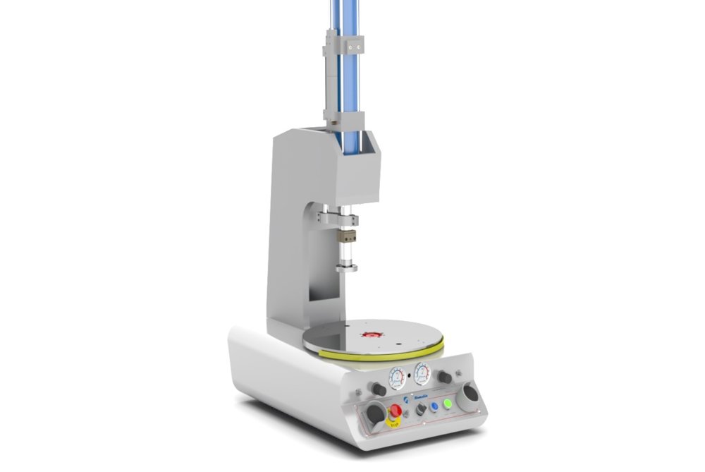
Press with electromechanical rotating table with support for reaction to axial thrusts.
Mechanically adjustable for clearance recovery.
Ground rotating disc in steel Fe 430 B - UNI 7070.
The press is available with six different structure configurations, to meet the most varied application needs.
The bending of the structures, even at the maximum press-force of the presses, is kept within contained values.
All surfaces are treated to ensure maximum corrosion resistance.
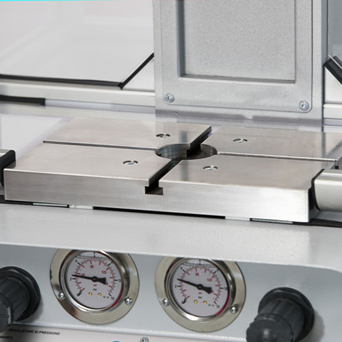
Made of steel Fe 430 B UNI 7070 with ground surface. Equipped with X or T slots (depending on the press model) for mould securing.
Depending on the needed power stroke and the required accessories, it is possible to install AP thrust (in line) or AX thrust (parallel structure) units.

They are available in three different configurations, to meet the different application needs and conformations of the piece.
All presses comply with the most recent safety regulations.

The pneumatic circuit is housed, depending on the press model, into the lower portion of the press, into a pneumatic side cabinet or in the press bed.
For operating the press and checking the working parameters.
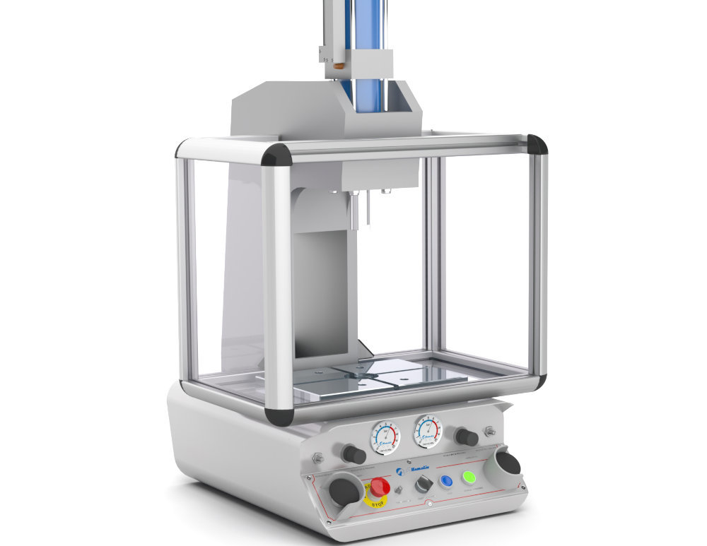
The CB type protection has the front part with free access, with the operator protected by the two-hand control.
The rear and side lexan® barriers then prevent third party access to the work area
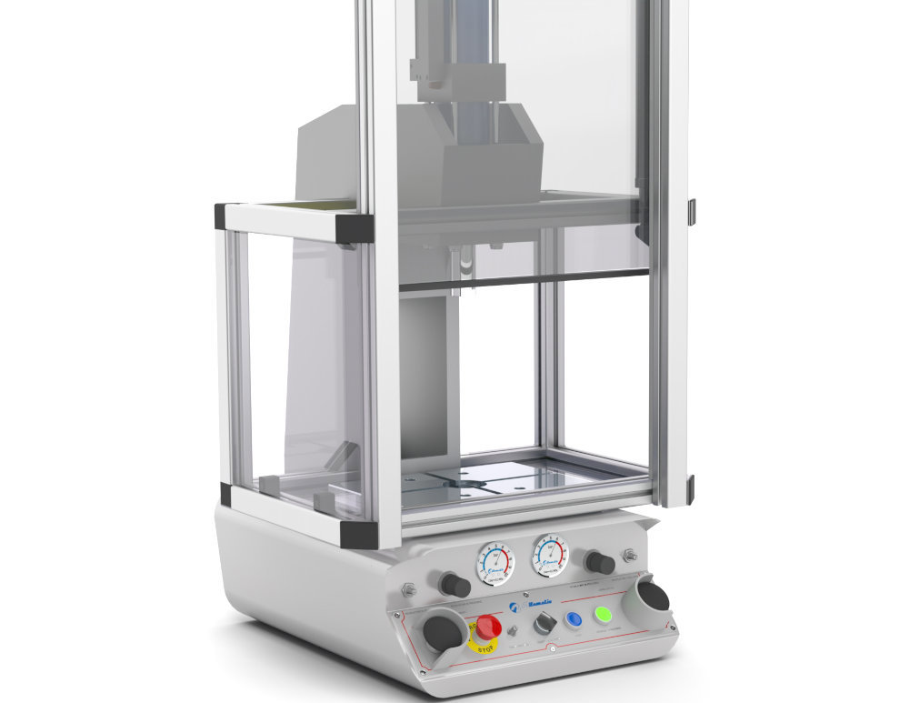
The CA type protection has the front part protected by a pneumatically operated mobile gate.
The rear and side lexan® barriers then prevent third party access to the work area.
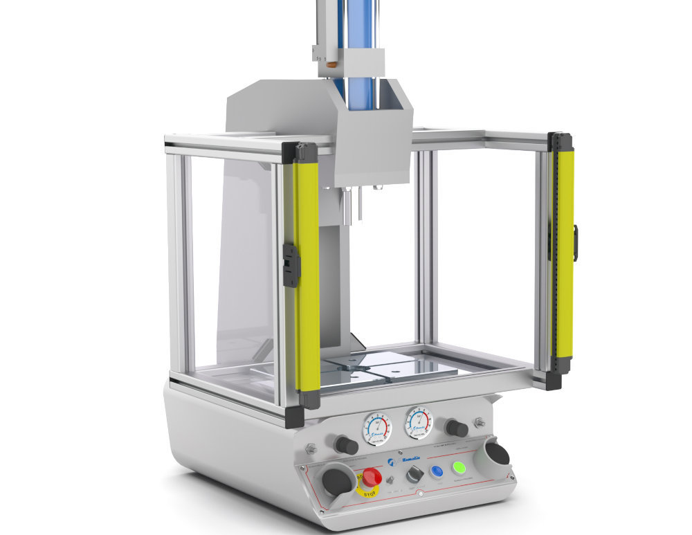
The CE type protection has the front part with free access, with the operator protected by photoelectric barriers.
The rear and side lexan® barriers then prevent third party access to the work area.
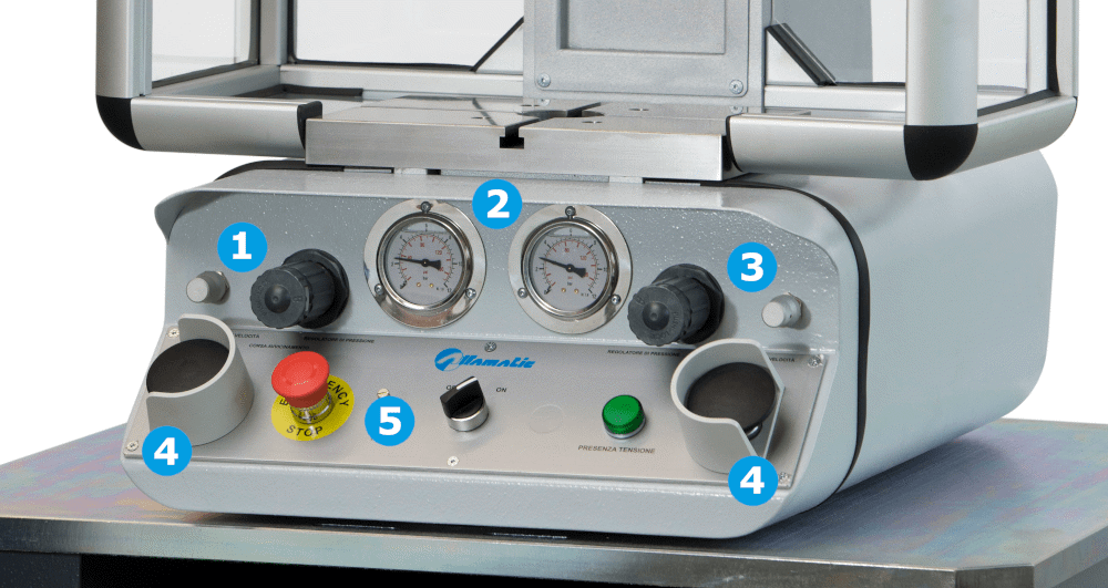
All controls at your fingertips.
For easy and effective control of the work cycle.
The presses can be equipped with electronic systems that monitor, piece by piece, the characteristics of the processing carried out.
They are based, depending on the model, on sensors for detecting pressure / force and the position of the press stem. From a comparison between the measured values and pre-established parameters, it is possible to determine, with precision, whether the characteristics of the piece made comply with the standard.
Depending on the degree of accuracy, they are available in different configurations:
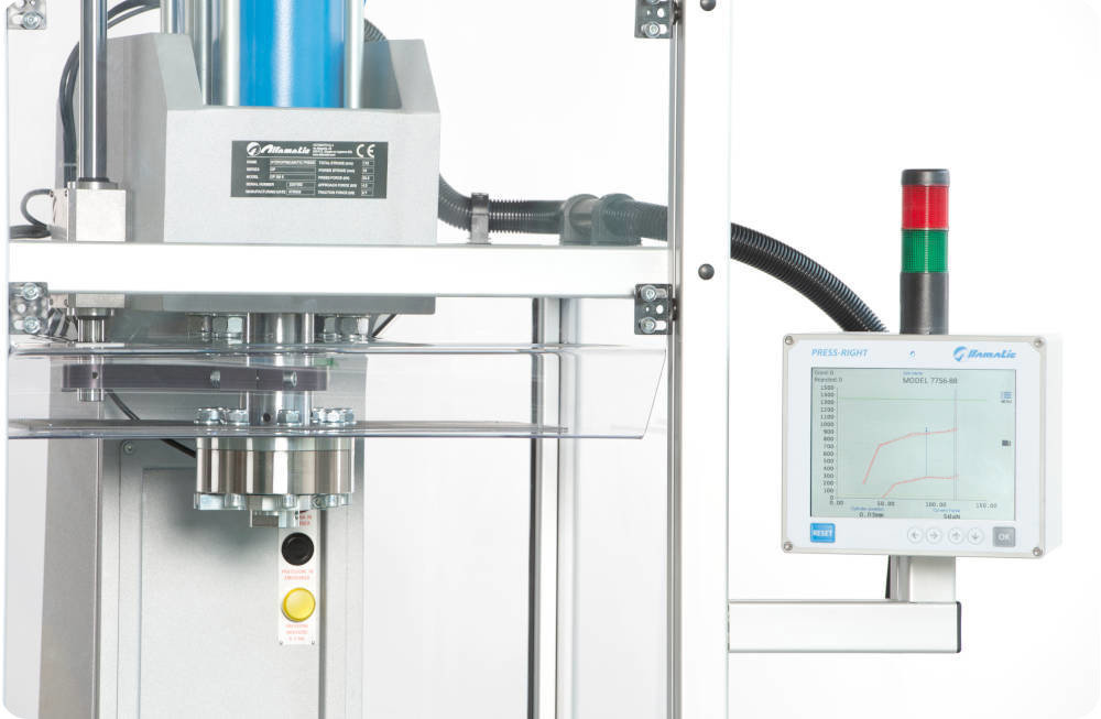
It continuously detects the position / force curve and verifies that it is contained within a suitably positioned continuous control band.
Two transducers: for position and force measurement.
A color 640 × 480 resolution display with Full touch is available for easy use. Slot for external SD memory.
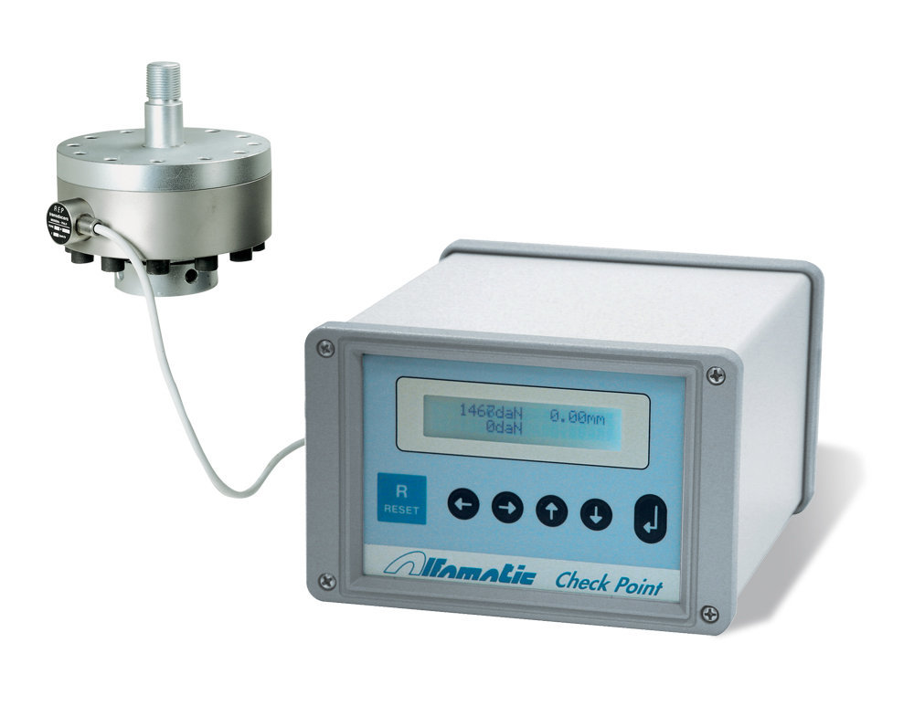
Connected to a single transducer, it displays its value in real time. It allows the control of the peak value and the stop of the press at a programmed value. RS 232 connection for reading and programming. Up to four programmable set points. 32 storable programs.
Functions:
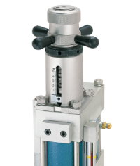
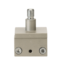
The device limits, with centesimal precision, the excursion of the front piston rod.
This device, with manual adjustment, allows to preset the lenght of power stroke.
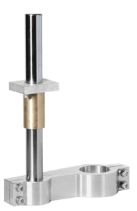
Complete with bracket, anti-rotation rod, guide bushing and bushing cap.
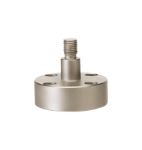
Equipped with nr. 4 axial holes for fixing the mold.
It converts female (standard) thread to male.
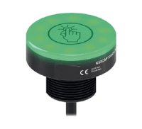
Ergonomic buttons in comfort version, touch-sensitive.
Radial coupling device for fixing the mold.
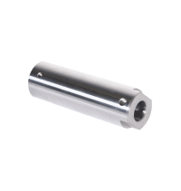
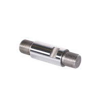
To interface with the stem of the press, it increases its length.
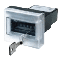
Totalizer of the number of cycles performed, equipped with button for manual reset.
The OP series presses can be supplied with three different command logics:

Approach and power stroke in sequence

Timed automatic return at the end of work

Power stroke with pneumatic spring reaction